![<?echo $_SERVER['SERVER_NAME'];?>](/template/twentyseventeen/skin/images/header.jpg)
Foreword
Automation and intelligence of welding production have become an important direction in the development of welding technology. In the process of intelligent welding, the application of sensors is one of the key technologies. Among them, optical sensors have high tracking accuracy, fast dynamic response and rich information, which is one of the most studied sensors. Image sensing has non-contact characteristics and is less affected by welding arc and electromagnetic field. It has been widely used in the field of welding and provides a powerful means for automation of welding operations. The compact size and low price of vision sensors such as CCDs make their industrial applications possible. At present, visual sensing and image processing technologies have been widely used in weld seam identification, fluid pool dynamic intelligent control, weld seam tracking, predictive welding organization, structure and performance [1-3].
In order to use the visual technology to identify the weld or extract the characteristics of the weld pool for weld tracking, penetration control, etc., an important step is to extract the characteristic parameters of the weld or the weld pool. For example, on a workpiece image, the weld grading and the gradation of the workpiece forming the weld are discontinuous, so the weld appears as an edge on the workpiece image. For the molten pool image, the difference in gray level between the molten pool and the arc is also reflected on the edge of the image, reflecting the shape characteristics of the molten pool. Therefore, the edge is an important feature quantity. Poggio et al. [4] defined edge detection as "mainly measurement, detection and localization of grayscale changes". The edge is related to but different from the boundary of the object in the image. To use optical sensing and image processing techniques for intelligent welding, the extraction of weld seams or weld pool edges is a necessary process.
In 1959, edge detection was first mentioned in the literature [5]. In 1965, LG Roberts first began systematic research on edge detection [6]. A lot of articles about edge detection will appear every year in the future. Most important articles are published in IEEE Trans. On Pattern Analysis and Machine Intelligence, CVGIP: Image Processing, IEEE Trans. On Image Processing, Journal of the ACM, etc. Although there are thousands of edge detection methods, none of them have universality and wide adaptability, and can be directly used in a specific application. Therefore, the characteristics of existing algorithms are found to be suitable for welding characteristics. The algorithm and the development of new algorithms for the welding process have certain practical significance.
1. Analysis of weld edge type characteristics
In image processing theory [7], image edge points may correspond to different physical meanings. According to the corresponding different physical meanings, the edges can be divided into the following four categories (as shown below):
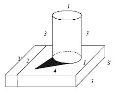
Image edge type
(1) Class 1 edge. As shown in Figure 1, the edge line labeled 1 is a line of intersection of two different curved surfaces or planes. The normal direction of the surface of the object at this point is discontinuous. On both sides of the type 1 edge line, the gray value of the image There are significant changes.
(2) 2 types of edges. Class 2 edge lines are produced by material types or color differences. The above figure consists of two different materials. Due to their different reflection coefficients to light, the gray scales on both sides of the 2 edge lines change significantly.
(3) Class 3 edges. The class 3 edge line is the boundary between the object and the background. There are two types of edge lines on the cylinder in the above picture, which are generally called outer contour lines. At the 3 types of edge points, the normal direction of the surface of the three-dimensional object is continuous, and the edge point appears because when the object is viewed from a certain angle of view, the three types of boundary points are the boundary between the object and the background. Since the object and the background differ greatly in terms of illumination conditions and material reflection coefficients, the gray scale of the image also changes significantly on both sides of the three types of edges. The edge marked with 3' in the figure is not only the boundary between the object and the background, but also the discontinuity of the normal on the upper surface of the object, but the reason for causing the gray jump on both sides is the former.
(4) 4 types of edges. 4 is the edge caused by the shadow. Since a certain part of the surface of the object is blocked by another object, it is not illuminated by the light source, and thus the gray value on both sides of the edge point is greatly different.
For joints before welding, either butt welds, beveled welds or lap welds exhibit two distinct edges, which can be considered as overlapping edges. For the weld pool, it exhibits a distinct edge profile corresponding to the shape of the weld pool. At the same time, the welding environment is more complicated, such as inconsistencies in the surface of the weldment (scratches, oxidation, marking, oil, etc.), as well as arc interference. For a highly reflective workpiece such as aluminum, there is also reflection of light, reflection of a welding torch, etc., making identification extremely difficult. Analyzing the characteristics of the weld and the weld pool, it can be seen that the edges of the weld environment include the 2, 3, and 4 types of edges described above. The effects of these factors must be considered when selecting and proposing new edge extraction algorithms.
2. Common edge extraction algorithm and its applicability in welding environment identification
As mentioned earlier, the method of edge extraction can be roughly divided into gradient detection methods (such as Roberts operator, Prewitt operator and Sobel operator), second derivative zero crossing point detection method, statistical method, wavelet multi-scale detection. , fuzzy mathematics methods, as well as mathematical morphology, neural network, edge flow method and other detection methods. So many algorithms can only say which one is better for a specific application area. In 1986, Canny [8] summarized the results of previous theories and practices, and proposed the Canny three criteria for edge detection: good detection results, good positioning and low repetition response to a single edge, and given their mathematical expressions. Based on the characteristics of the welding environment, the applicability of the existing edge extraction algorithm to the welding environment identification is analyzed.
2.1 differential operator
2.1.1 Gradient operator
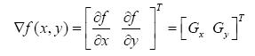
The gradient corresponds to the first derivative, and the corresponding gradient operator corresponds to the first derivative operator. For a continuous function f(x, y), its gradient at (x, y) is defined as follows:
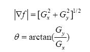
A gradient is a vector whose magnitude and phase are:
The algorithm needs to calculate the position of each pixel, so the amount of calculation is very large. In practice, a small template is often used to approximate the convolution operation, and Gx and Gy each use a template. The commonly used template is the Robert operator. The more common commonly used templates are Prewitt operator, Sobel operator, and Kirsch operator. The quality of these kinds of operators depends on the structure of the noise. If the noise is the same at each point, then the Prewitt operator is better. If the noise near the edge is 2 times along the edge, then The Sobel operator is better.
Thus the gradient operator takes into account both the amplitude and the direction parameters. In the identification of the welding environment, we hope to obtain the information of the weld in real time, and at the same time hope to predict the direction of the weld forward. So the gradient operator gives us a viable method. However, the gradient operator is sensitive to noise, which identifies many false edges for complex welding environments. Therefore, the gradient operator is not ideal for the edge extraction of the weld seam. You can improve the results by smoothing the image first, smoothing out the edges that are close together, and affecting the positioning of the edges. The edges obtained by convolution with these templates may be a few points rather than a point, so two factors should be considered at the same time. The edge pixels are not only larger than the threshold, but also the gradient in the gradient direction is larger than its The former and its latter, this method is called non-extreme suppression.
Next page
Fda Approved Rubber Ball,Openable Rubber Ball,Silicone Vibration Damper Ball
Neway Rubber Products Co., Ltd. , http://www.lxrubbers.com